Tag: Fuel Mixture Cooler

  • Gas Engine Intercooler: Its Role and Field Inspection

    Gas Engine Intercooler: Its Role and Field Inspection

    In the previous article, we looked at how a turbocharger uses exhaust-gas energy to compress air or an air-fuel mixture.

    When a gas is compressed by the turbocharger compressor, both its pressure and temperature increase.

    An intercooler lowers the temperature of the compressed air or mixture and helps provide suitable intake conditions for the engine.

    A change in intercooler performance can affect the mixture temperature, differential pressure across the intercooler, engine output, and combustion condition.

    This article explains how an intercooler removes heat and what should be checked in the field, including temperature, differential pressure, internal fouling, and cooling-water leakage.

    Related article | How Does a Gas Engine Turbocharger Work?


    1. What Does an Intercooler Do?

    When air or an air-fuel mixture is compressed by the turbocharger, its temperature rises.

    At the same pressure, a higher-temperature gas has a lower density.. This can reduce the mass of air or mixture contained in a given volume and can also affect engine output, combustion stability, and the margin against knocking.

    The intercooler cools the compressed air or fuel-gas/air mixture before it enters the engine.

    In some premixed gas engines I have worked with, fuel gas and air were mixed before entering the turbocharger. The compressed mixture was then cooled in the intercooler before being supplied to the engine.

    The basic flow was as follows:

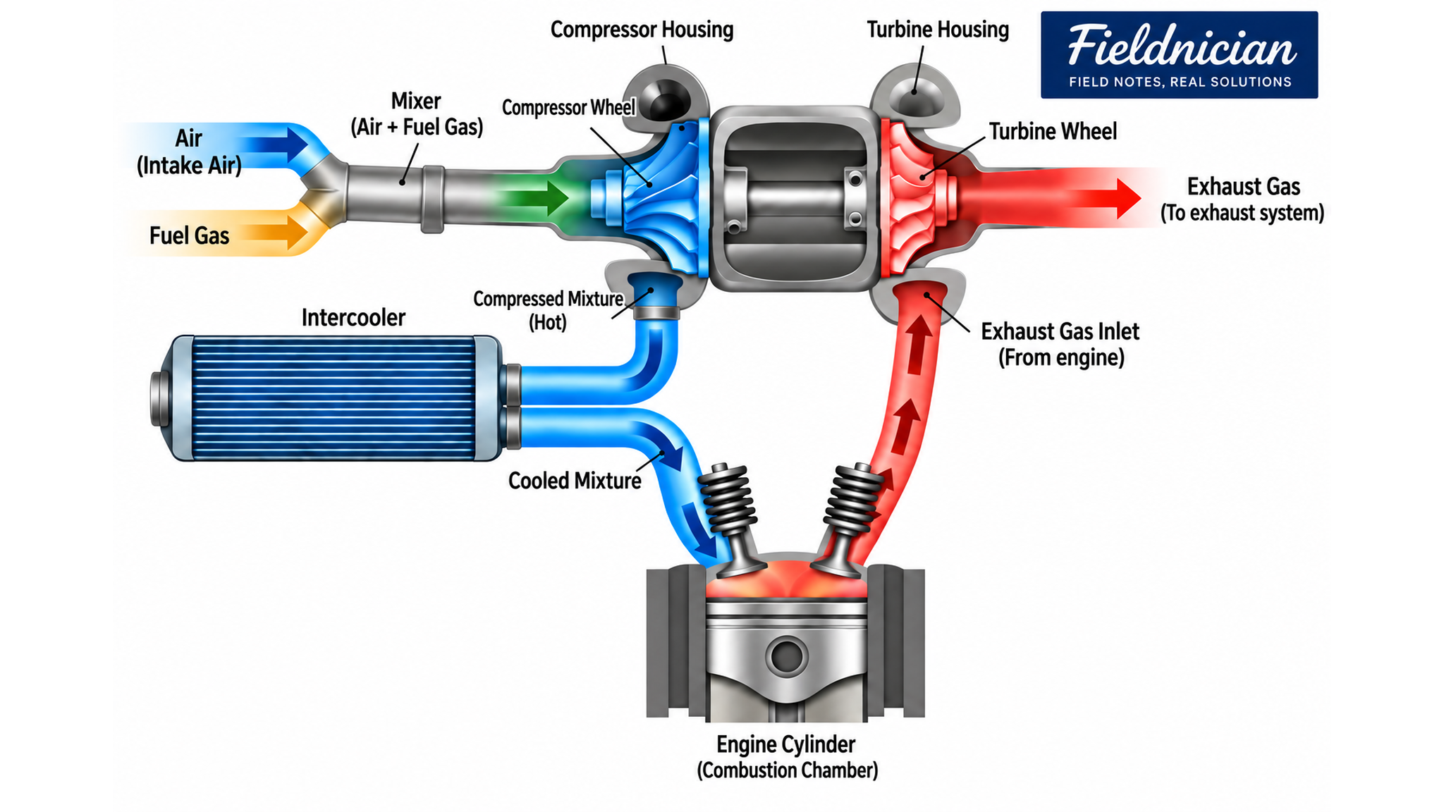
    Fuel gas and air → Mixing → Boosting by the turbocharger → Cooling in the intercooler → Intake manifold → Cylinders

    In this type of engine, the intercooler may also be referred to as a fuel mixture cooler.

    In other engine designs, only air passes through the turbocharger and intercooler before fuel gas is added farther downstream.

    The fluid passing through the intercooler must therefore be confirmed using the fuel-gas and intake-system diagrams for the specific engine.


    2. How Does an Intercooler Remove Heat?

    In the water-cooled intercoolers I have worked with, the hot fuel-gas/air mixture and cooling water flowed through separate passages.

    The two fluids did not mix directly. Heat moved from the hot mixture to the cooling water through tubes, plates, or other heat-transfer surfaces inside the intercooler.

    The cooled mixture then moved toward the engine, while the cooling water carried the absorbed heat through the cooling-water system.

    Depending on the plant configuration, this heat may be transferred to a heat-recovery system or rejected through a radiator or another cooling device.

    Air-cooled intercoolers may also be used in some installations.

    The actual cooling-water circuit and heat-rejection or heat-recovery arrangement depend on the engine design and the plant cooling system.
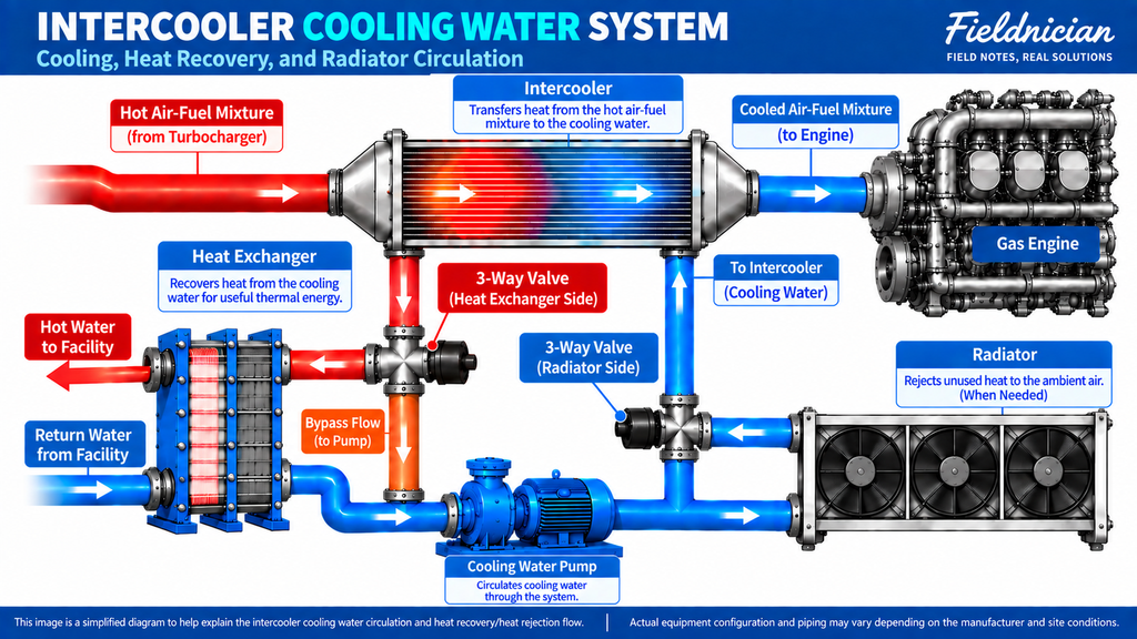
    Gas engine intercooler cooling-water system with heat recovery and radiator circulation
    Simplified diagram of intercooler cooling-water circulation, heat recovery, and radiator heat rejection.

    3. What Do the Inlet and Outlet Temperatures Show?

    The intake-side inlet and outlet temperatures can be compared to evaluate how much the air or mixture is cooled as it passes through the intercooler.

    Under normal operating conditions, the outlet temperature should generally be lower than the inlet temperature.

    However, the temperature difference alone does not provide a complete evaluation of intercooler performance.

    It can change with:

    • Engine load
    • Intake mass flow
    • Turbocharger compression conditions
    • Cooling-water inlet temperature
    • Cooling-water flow
    • Ambient conditions

    For this reason, temperature data should be compared at a similar engine load and under comparable operating conditions.

    An outlet temperature that is higher than usual does not always mean that the intercooler itself is damaged. High cooling-water temperature, insufficient circulation, changes in turbocharger operation, or a faulty temperature sensor can produce a similar result.

    Excessive cooling can also create problems. If the air or mixture is cooled below its dew point, moisture may condense inside the intercooler or intake piping.

    The outlet temperature should therefore be maintained within the operating range specified by the engine manufacturer.


    4. What Is the Difference Between Pressure and Differential Pressure?

    The inlet and outlet pressures indicate the pressure at each measurement point.

    Differential pressure is the difference between the two values:

    Differential pressure = Intercooler inlet pressure − Intercooler outlet pressure

    When air or an air-fuel mixture passes through the intercooler, a certain amount of pressure loss occurs because of flow resistance.

    If the differential pressure becomes higher than usual at the same engine load, the resistance inside the intercooler or connected piping may have increased.

    Possible causes include:

    • Fouling in the air or mixture passages
    • A restricted flow path
    • Obstruction in the connected piping
    • A valve that is not fully open
    • A problem with the pressure-sensing lines
    • A faulty pressure sensor

    Differential pressure also changes with gas flow, density, engine load, and measurement location.

    Values measured at different loads should not be compared directly. The inlet and outlet pressures and their differential should be compared under similar operating conditions.

    A low outlet pressure alone does not prove that the intercooler is blocked. Turbocharger performance, an upstream air-filter restriction, piping leakage, and engine load can also affect the measured pressure.


    5. What Should Be Checked When the Mixture Temperature Is High?

    If the mixture temperature downstream of the intercooler is higher than usual, the entire heat-transfer path should be checked before identifying the intercooler as the cause.

    First, check the temperature entering the intercooler and the turbocharger operating condition.

    Next, check the cooling-water inlet and outlet temperatures, pump operation, valve position, and any part of the system that could affect cooling-water circulation.

    Possible causes include:

    • High cooling-water inlet temperature
    • Reduced cooling-water flow or abnormal circulation
    • Fouling or deposits in the cooling-water passages
    • Fouling on the air or mixture side
    • A change in turbocharger outlet temperature
    • A change in boost conditions
    • A faulty temperature sensor or wiring problem

    Cooling-water pressure should not be treated as the same measurement as cooling-water flow.

    A pressure change alone does not prove that the flow is insufficient. The sensor location and cooling-system arrangement must be considered, and temperature, flow, pump condition, and valve position should be compared whenever those measurements are available.


    6. How Should Fouling and Cleaning Be Evaluated?

    Fouling on the air or mixture side can increase flow resistance and affect the differential pressure across the intercooler.

    Oil mist, dust, fuel-related deposits, or other contaminants may accumulate on the gas-side passages and heat-transfer surfaces.

    Deposits, scale, corrosion products, or sludge on the cooling-water side can reduce heat transfer and increase the outlet temperature of the air or mixture.

    If the differential pressure continues to rise or cooling performance gradually decreases under comparable operating conditions, the internal condition of the intercooler may need to be inspected.

    Cleaning should not be performed only because the outlet temperature is high.

    Cooling-water temperature and circulation, turbocharger operation, operating load, and instrument readings should first be checked to determine whether fouling is a likely cause.

    If chemical cleaning is required, the cleaning agent must be compatible with:

    • The intercooler material
    • The heat-transfer surfaces
    • Gaskets and seals
    • The type of contamination

    The manufacturer’s cleaning limits and procedures should be followed.

    After cleaning, the intake side must be checked to ensure that no cleaning liquid or foreign material remains. The intercooler should be properly dried before it is returned to service.

    Temperatures and differential pressure should then be compared with the values recorded before cleaning at a similar engine load.


    7. Is Water Inside the Intercooler Always a Coolant Leak?

    Water found inside an intercooler or intake pipe does not always indicate cooling-water leakage.

    Air naturally contains water vapor. If warm and humid air is cooled below its dew point inside the intercooler, some of that vapor can condense into liquid water.

    The amount of condensate can change according to:

    • Ambient temperature and humidity
    • Intake temperature
    • Cooling-water temperature
    • Engine load
    • Operating duration

    However, cooling water can also enter the air or mixture side if a tube, plate, seal, or another internal heat-transfer surface is damaged.

    To distinguish condensate from cooling-water leakage, the following should be checked together:

    • A continuous decrease in cooling-water level or an increase in makeup-water consumption
    • Changes in cooling-system pressure
    • An increase in the amount of automatically supplied makeup water
    • Color or chemical characteristics of the collected liquid
    • Moisture in the piping downstream of the intercooler
    • Results of a leak test or pressure test

    Condensate and cooling-water leakage have different causes and require different corrective actions. The presence of water alone is not enough to identify the source.


    8. Where Can Intercooler Leakage Occur?

    An intercooler can develop leakage on the air or mixture side, the cooling-water side, or internally between the two circuits.

    An external leak on the air or mixture side may occur at:

    • Piping connections
    • Flanges
    • Gaskets
    • Clamps
    • Inspection covers
    • Intercooler casing joints

    A cooling-water leak may appear around cooling-water connections, gaskets, drain points, or the intercooler casing.

    If an internal heat-transfer surface is damaged, cooling water may enter the air or mixture passage. It can then move through the intake piping toward the engine.

    Depending on the relative pressures of the two circuits, air or mixture may also enter the cooling-water side.

    If the cooling-water level or system pressure continues to decrease without a visible external leak, internal intercooler leakage should be considered.

    The piping downstream of the intercooler, the engine intake path, exhaust condition, and lubricating-oil condition may also need to be checked.

    At sites equipped with automatic cooling-water makeup, a leak may not immediately appear as a low level. The makeup quantity and its trend should therefore be monitored separately.

    If a premixed air-fuel charge passes through the intercooler, an external leak can release a flammable mixture. It must not be treated as an ordinary compressed-air leak.


    9. What Should Be Checked in the Field?

    The intercooler cannot normally be opened during operation to inspect its internal condition.

    Its condition must therefore be evaluated by comparing operating data recorded at a similar engine load and under similar conditions.

    Important inspection items include:

    • Air or mixture temperature at the intercooler inlet and outlet
    • Air or mixture pressure at the inlet and outlet
    • Differential pressure across the intercooler
    • Cooling-water inlet and outlet temperatures
    • Cooling-water pressure and circulation condition
    • Cooling-water pump operation
    • Cooling-water valve position
    • External leakage on the air, mixture, and cooling-water sides
    • Cooling-water level and makeup quantity
    • Engine load and boost pressure
    • Related temperature and pressure sensor condition
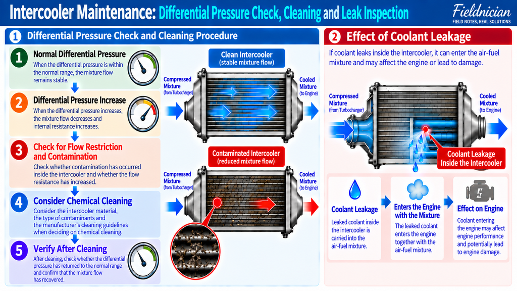
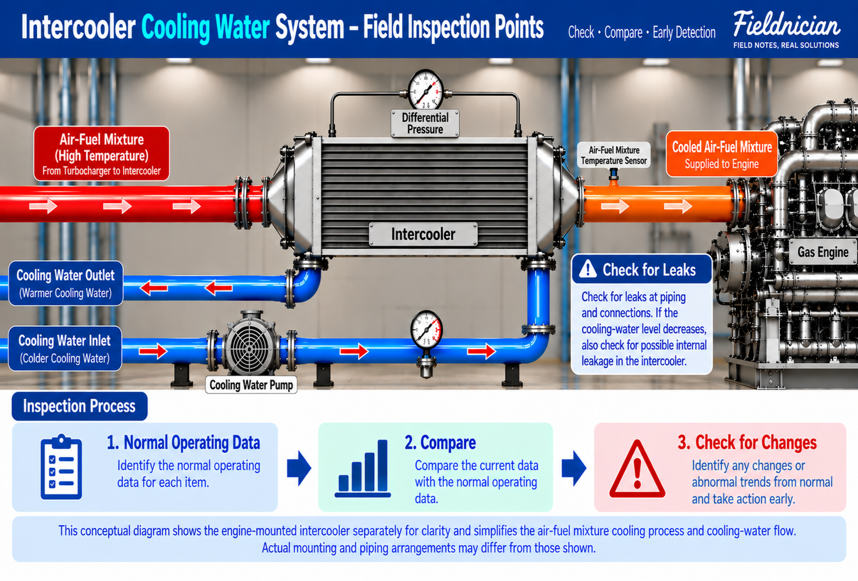
    Intercooler differential pressure check, cleaning process, and internal coolant leakage inspection
    Intercooler maintenance overview showing differential pressure changes, contamination and cleaning checks, and the possible effects of internal coolant leakage.

    If the outlet temperature is high, the cooling-water condition, intercooler fouling, turbocharger operation, and temperature sensor should be checked in sequence.

    If the differential pressure has increased, the intercooler passages, connected piping, sensing lines, and pressure sensors should all be checked.

    A single measurement should not be used to determine the cause. Temperature, pressure, differential pressure, engine load, and operating trends must be considered together.


    10. What Safety Precautions Are Required?

    Even after the engine has stopped, the cooling-water system may remain hot and pressurized.

    Before opening cooling-water piping or intercooler connections, confirm that the temperature has fallen to a safe level and that the internal pressure has been safely released.

    Differential pressure across the air or mixture side is meaningful when gas is actually flowing. Measurements taken during operation must be performed without contacting rotating parts, hot surfaces, or pressurized piping.

    If a flammable premixed charge passes through the intercooler, the fuel supply must be isolated before the piping or intercooler is opened.

    Residual gas must be removed using the approved procedure, adequate ventilation must be provided, and the gas concentration must be confirmed before work begins.

    Disassembly, cleaning, leak testing, and pressure testing must follow:

    • The engine and intercooler manufacturer’s procedures
    • The applicable system drawings
    • The site permit-to-work requirements
    • The site gas-safety procedures

    After maintenance, check the airtightness of the intake or mixture side, the cooling-water connections, valve positions, and instrument connections before restarting the engine.


    Conclusion

    An intercooler is a heat exchanger that cools air or an air-fuel mixture after it has been compressed by the turbocharger.

    Lowering the intake temperature helps provide suitable intake density and supports stable engine output and combustion.

    In the field, the air or mixture temperature, cooling-water condition, differential pressure, and leakage should be compared with normal operating data recorded under similar conditions.

    Temperature, pressure, and differential pressure represent different conditions and must be interpreted separately.

    Water found inside the intercooler is not always caused by cooling-water leakage. Condensate formed under certain operating conditions must be distinguished from an internal leak by checking cooling-water loss, automatic makeup quantity, liquid characteristics, system pressure, and test results.

    The intercooler should not be evaluated as an isolated component. Its condition must be considered together with the turbocharger, intake piping, cooling-water system, sensors, and control devices.
  • How Does a Gas Engine Turbocharger Work?

    How Does a Gas Engine Turbocharger Work?

    In the previous article, we looked at how fuel gas and air travel through their separate supply systems, mix, and enter the engine.

    To produce more power, a gas engine must burn more fuel while maintaining stable combustion.

    Simply increasing the amount of fuel is not enough. A corresponding mass of air must also be supplied.

    A turbocharger uses energy from the engine’s exhaust gas to compress the air or mixture entering the engine.

    Changes in turbocharger performance can affect boost pressure and engine output as well as exhaust gas temperature and combustion stability.

    In this article, we will look at the construction and operating principles of a turbocharger, the conditions to monitor during operation, and the main items checked during scheduled disassembly and inspection.

    Related article|How Do Fuel Gas and Air Enter a Gas Engine?


    1. Why Does a Gas Engine Need a Turbocharger?

    A naturally aspirated engine relies on the pressure difference created by piston movement to draw outside air into the cylinders.

    However, there is a limit to the mass of air that atmospheric pressure and piston movement alone can supply.

    A turbocharger raises the pressure in the intake system, allowing a greater mass of air to enter cylinders of the same size.

    When more air is available, the engine can burn a corresponding amount of additional fuel and produce the required output.

    A turbocharger uses energy from the engine’s exhaust gas instead of relying on a separate electric motor to drive the compressor.

    In this way, part of the energy remaining in the exhaust gas is used to rotate the turbine and compress the intake air or mixture.


    2. What Are the Main Components of a Turbocharger?

    A turbocharger consists mainly of a turbine, a compressor, and a center housing.

    The turbine is installed on the exhaust side, while the compressor is installed on the intake side.

    The turbine wheel and compressor wheel are connected by a common shaft and rotate together around the same axis.

    The center housing contains the shaft that connects the two wheels and the bearings that support the rotating assembly.

    The basic power-transfer path can be summarized as follows:

    Exhaust gas
    → Turbine wheel
    → Shaft
    → Compressor wheel
    → Boosted air or mixture

    The detailed construction, size, bearing and sealing arrangements, lubrication method, and cooling method vary depending on the engine and turbocharger model.


    3. How Does Exhaust Gas Drive the Turbine?

    Exhaust gas leaving the cylinders still contains pressure and thermal energy.

    After passing through the exhaust valves, the gas travels through the exhaust manifold and enters the turbine housing.

    The turbine housing directs the exhaust gas toward the turbine-wheel blades, causing the turbine wheel to rotate.

    The turbine wheel transmits this rotation through the shaft to the compressor wheel on the opposite side.

    After passing through the turbine, the exhaust gas continues through the exhaust system. Depending on the installation, some of its remaining heat may also be recovered.

    Restricted exhaust flow, deposits, or damage on the turbine side can affect turbocharger rotation and boost performance.


    4. What Does the Compressor Compress?

    As the compressor wheel rotates, it accelerates the air or mixture entering the intake system and raises its pressure.

    The turbine and compressor handle separate gas streams. Only mechanical rotation is transmitted between them through the common shaft.

    What passes through the compressor depends on the engine’s fuel-supply system and the location of the gas mixer.

    In some of the premixed gas engines I have worked with, the fuel gas and air were mixed before entering the compressor.

    In this arrangement, the turbocharger compressor boosts a combustible mixture of fuel gas and air.

    The boosted mixture was cooled in a fuel mixture cooler and then supplied to each cylinder through the intake manifold.

    The basic flow was as follows:

    Fuel gas and air
    → Mixing
    → Boosting by the compressor
    → Cooling in the fuel mixture cooler
    → Intake manifold
    → Cylinders

    If the mixer or fuel-supply device is installed downstream of the turbocharger, the compressor may handle air only.

    Some engines supply air first and introduce fuel gas at the intake ports or closer to the cylinders.

    Before inspecting the turbocharger or intake piping, technicians should determine whether each section contains air or a combustible premixed charge by checking the fuel-gas and intake-system diagrams.

    Related article|The Role of a Gas Engine Intercooler and What to Inspect (Coming Soon)


    5. Why Are the Shaft, Bearings, and Lubrication Important?

    The shaft connecting the turbine and compressor wheels rotates at very high speed while the engine is operating.

    The bearings support the shaft and rotating assembly while controlling radial and axial movement.

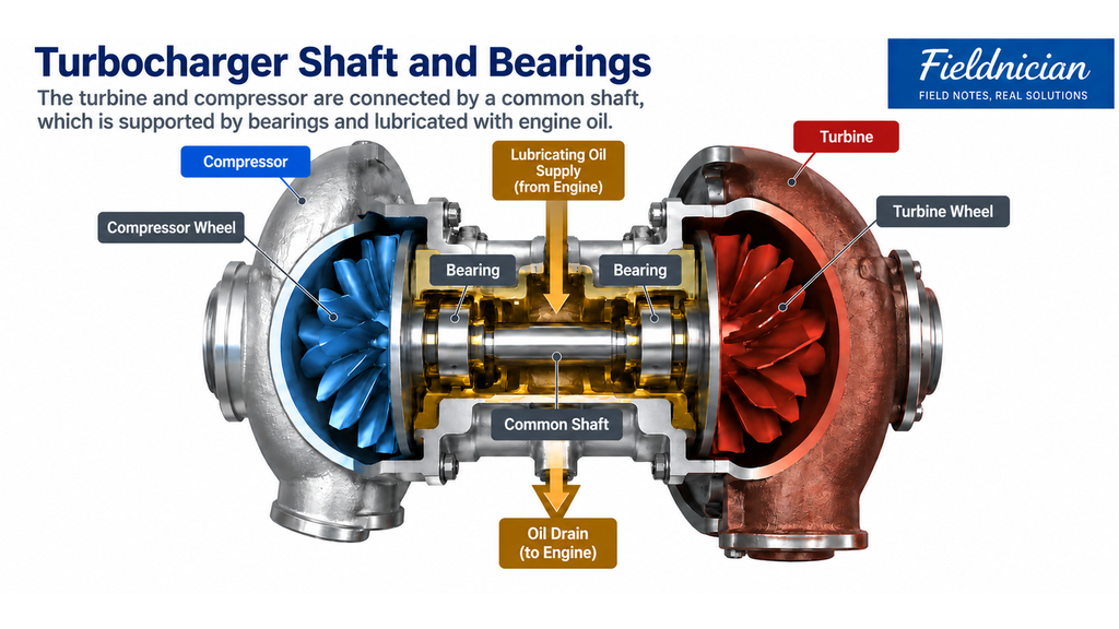
    Lubricating oil reduces friction between the bearings and shaft, carries away heat, and allows the rotating assembly to operate smoothly.

    Cutaway turbocharger diagram showing the compressor and turbine connected by a common shaft supported by bearings, with engine-oil lubrication and oil drain.
    The compressor and turbine are connected by a common shaft supported by bearings and lubricated with engine oil.

    Insufficient oil supply or contaminated lubricating oil can cause wear or damage to the bearings and shaft.

    As shaft and bearing wear increases, internal clearances and rotating conditions may change, resulting in abnormal noise or vibration.

    Inspection should therefore include not only the shaft and bearings but also the oil-supply and drain lines, external oil leakage, and possible restrictions.

    If the turbocharger has a separate cooling circuit, the coolant supply and possible leakage should also be checked according to the manufacturer’s procedure.


    6. How Are Intake Cooling and Boost Pressure Related?

    Compressing air or an air–fuel mixture increases its temperature.

    At the same pressure, a higher temperature lowers the density of the intake gas, so less mass can occupy the same volume. Higher intake temperature can also affect the margin against knock and abnormal combustion.

    For this reason, many turbocharged engines use an intercooler or fuel mixture cooler downstream of the turbocharger.

    The cooler transfers heat from the compressed air or mixture to cooling water or ambient air.

    Reducing the intake temperature increases density and helps supply the required mass of air or mixture to the cylinders.

    When the turbocharger compresses the intake charge, the pressure in the intake system can rise above atmospheric pressure. This increased intake pressure is generally referred to as boost pressure.

    As engine load increases, demand for fuel and air rises, and exhaust-gas flow and energy may also increase. This can change turbine and compressor speed and increase boost pressure.

    However, boost pressure and the actual mass flow of air or mixture are not the same.

    Even at the same boost pressure, the mass entering the cylinders may vary with intake temperature, gas composition, piping resistance, and engine operating condition.

    Boost pressure may be controlled by a wastegate, bypass system, or another device, depending on the engine design.

    Boost pressure should therefore not be used by itself to assess the condition of the turbocharger or the engine’s combustion.

    Related article|How Does Mixture Boost Pressure Affect a Gas Engine? (Coming Soon)


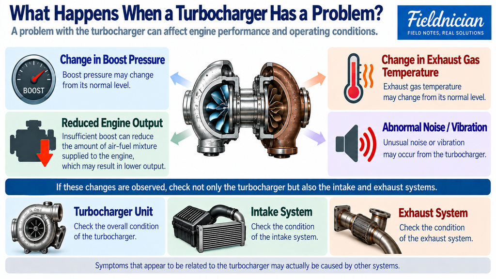
    7. What Changes Can Indicate a Turbocharger Problem?

    If turbocharger performance deteriorates, the engine may not receive enough boosted air or mixture.

    The following changes may appear during operation:

    • A change in boost pressure
    • Reduced engine output
    • Changes in exhaust gas temperature
    • Abnormal turbocharger noise or vibration
    • Lubricating-oil leakage
    • Contamination in the intake or exhaust system

    However, these changes do not automatically mean that the turbocharger itself has failed.

    A restricted air filter or intake pipe, an intake leak, fouling or increased differential pressure across the intercooler or fuel mixture cooler, increased exhaust-system resistance, and sensor or control-device faults can produce similar symptoms.

    Turbocharger problem infographic showing changes in boost pressure, reduced engine output, exhaust gas temperature changes, abnormal noise or vibration, and checks of the turbocharger, intake system, and exhaust system.
    : Turbocharger problems can affect boost pressure, engine output, exhaust gas temperature, noise, and vibration. The turbocharger, intake system, and exhaust system should be checked together.

    During operation, boost pressure, intake temperature, exhaust gas temperature, engine output, and available turbocharger data should be compared with normal values at a similar load.

    Technicians should also listen for unusual changes in high-frequency sound, rubbing noise, or vibration around the turbocharger.

    With the engine stopped, inspect the intake and exhaust connections, clamps, flanges, cooler connections, and lubricating-oil lines for leakage, movement, or deformation.

    Even when the rotating assembly can be checked without completely disassembling the turbocharger, the engine must first be stopped and secured against starting. The inspection must then follow the manufacturer’s procedure.


    8. When Should a Turbocharger Be Disassembled and Inspected?

    A turbocharger is not disassembled only after a fault occurs.

    Even when no obvious abnormal condition is present, it should be disassembled and inspected at the operating-hour interval specified by the engine or turbocharger manufacturer.

    If abnormal noise or vibration, or an unusual change in boost pressure or engine output, appears during operation, an additional inspection may be required before the scheduled interval.

    The decision to disassemble the turbocharger and the required maintenance scope should consider:

    • Current operating condition
    • Maintenance history
    • Fuel type and operating environment
    • Contamination condition
    • Manufacturer’s inspection criteria

    After high-load operation, the turbocharger may remain at a high temperature.

    If the manufacturer specifies an unloaded running period, cooldown procedure, or shutdown sequence, it should be completed before the engine is stopped. Inspection should begin only after the turbocharger has reached a safe condition.


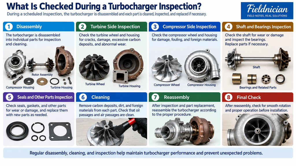
    9. What Should Be Checked After the Turbocharger Is Disassembled?

    After the turbocharger has been disassembled, inspect the turbine-wheel and compressor-wheel blades for damage and abnormal wear.

    The shaft should be checked for wear and damage, while the bearings, seals, and internal clearances should also be inspected.

    The inspection may include:

    • Damage to the turbine and compressor wheels
    • Blade wear and deformation
    • Shaft wear and damage
    • Bearing and seal condition
    • Radial and axial clearances
    • Contact marks between rotating and stationary parts
    • Oil and carbon deposits
    • Damage to the nozzle ring or other fitted components
    • Contamination or restriction in the oil-supply and drain passages
    Turbocharger inspection infographic showing disassembly, turbine and compressor component inspection, shaft and bearing checks, seals, cleaning, reassembly, and a final operational check.
    A scheduled turbocharger inspection includes disassembly, component checks, cleaning, replacement of worn or damaged parts when necessary, reassembly, and a final operational check.

    Where required, rotor balance should be checked using the method specified by the manufacturer. The wheels and other critical components may also need to be inspected for cracks.

    Parts that exceed the manufacturer’s limits should be replaced.

    Reusable parts should be cleaned using an approved method and inspected again before a reuse decision is made.

    Because a turbocharger contains a high-speed rotating assembly, external appearance alone is not enough to determine whether a part can be reused.

    Measurements, balancing, crack inspection, and assembly must follow the manufacturer’s limits, required equipment, and maintenance procedures for that turbocharger model.


    10. What Should Be Checked After Maintenance?

    After the turbocharger has been serviced and assembled, check the lubricating-oil supply and drain lines, intake and exhaust piping, and all related connections.

    Before the engine is started or loaded, complete the startup, oil-priming, or pre-lubrication procedure specified by the manufacturer and confirm that oil can reach the bearing system.

    If the turbocharger has a separate cooling circuit, also check the coolant piping and possible leakage.

    After the engine is started, compare the following items with the data recorded before maintenance:

    • Boost pressure
    • Intake-air or mixture temperature
    • Engine output
    • Exhaust gas temperature
    • Abnormal turbocharger noise or vibration
    • Lubricating-oil supply and drainage
    • External oil leakage
    • Leakage at intake and exhaust connections

    Rather than checking only whether each value falls within its normal range, compare pre-maintenance and post-maintenance data under similar loads and operating conditions.

    If unusual noise, vibration, or lubricating-oil leakage appears, determine the cause before continuing operation.

    Follow the engine and turbocharger manufacturer’s requirements for post-maintenance checks and operating confirmation.


    Conclusion

    A turbocharger uses energy from the engine’s exhaust gas to rotate a turbine and drive a compressor through a common shaft.

    The compressor then increases the pressure of the air or mixture supplied to the engine.

    Stable operation depends on the condition of the shaft and bearings, correct lubrication, and the condition of the intake, exhaust, and cooling systems.

    During field inspection, boost pressure, engine output, exhaust gas temperature, noise, and vibration should be evaluated together with the air filter, piping, cooler, exhaust system, and lubricating-oil system.

    A condition that appears to be a turbocharger problem may be caused by another part of the intake, exhaust, or control system.

    The turbocharger should also be disassembled and inspected at the maintenance interval specified by the manufacturer. After maintenance, operating data should be compared under similar conditions to confirm that normal performance has been restored.